


Coefficient of Thermal Expansion of Concrete
Part# AFCT2
Available Factory Direct
Email us for a quote
Simple
Measure the Coefficient of Thermal Expansion of Portland Cement Concrete easily using Pine’s system. Select the desired test parameters. Place the preconditioned specimen in a test fixture. Place the specimen and the test fixture in the bath. Then, run the test. The computer controls the test and automatically saves the temperature, displacement, and time data.
Relevance
Concrete pavement designers use the Coefficient of Thermal Expansion (CTE) of Portland Cement Concrete to account for the stresses caused by temperature changes experienced by the pavement structure. The Mechanistic Empirical Design Guide specifies its use.
Productive
Because running AASHTO T 336 is time consuming, increase productivity by using the full capacity of the Pine system. Test up to three concrete cylinders simultaneously to increase system throughput.
System Components
- Water-bath
- Heating/cooling circulator
- Up to three (3) specimen fixtures
- Up to three (3) verification specimens
- One (1) calibration specimen
- Interface electronics
- Temperature measurement instrumentation
- Control software
- A computer, typically provided by the user
Flexible
Pine’s system allows for alternative testing protocols because most of the test parameters are programmable.
Data
The system exports data via a Pine-provided Excel workbook. Reports are formatted for AASHTO T 336 and TEX-428-A.
Standard/Compliance
Brochure
Power:
AFCT2:
100-240 VAC, 1 Amp, 60 Hz, 1 ph
Circulator:
115 VAC (±10%), 16.4 Amps, 60 Hz, 1ph
230 VAC (±10%), 12.5 Amps, 50 Hz, 1ph
Shipping Weight:
Approximately 136 kg (300 lbs)
Footprint:
Approximately 45″ D x 35″ W x 35.5″ H for the water-bath/circulator system
Allow additional space along the unit for an operator to load specimens.
Data Output:
Formatted Excel® Spreadsheet
Time, Temperature, Change in Length, and CTE Value
Water Bath:
838 mm length x 406 mm width x 889 mm high (33” x 16” x 35”)
Capacity: 68 liters / 18 gallons (holds up to three fixtures)
Circulator:
Temperature Range:
10° – 50°C (50°-122°F) with a resolution of ± 0.1°C
Performance:
Heating: 10° – 50° C ~3.5 hour
Cooling: 50° – 10° C ~2 hour
Specimen Size:
Diameter: 75 mm – 160 mm
Length: 177.8 mm (7.0”) ± 2.5 mm (± 0.1”) [175.3 mm – 180.3 mm]
The system can handle 168 to 188-mm long specimens, but lengths outside of 175.3 to 180.3 mm require custom frame standards.
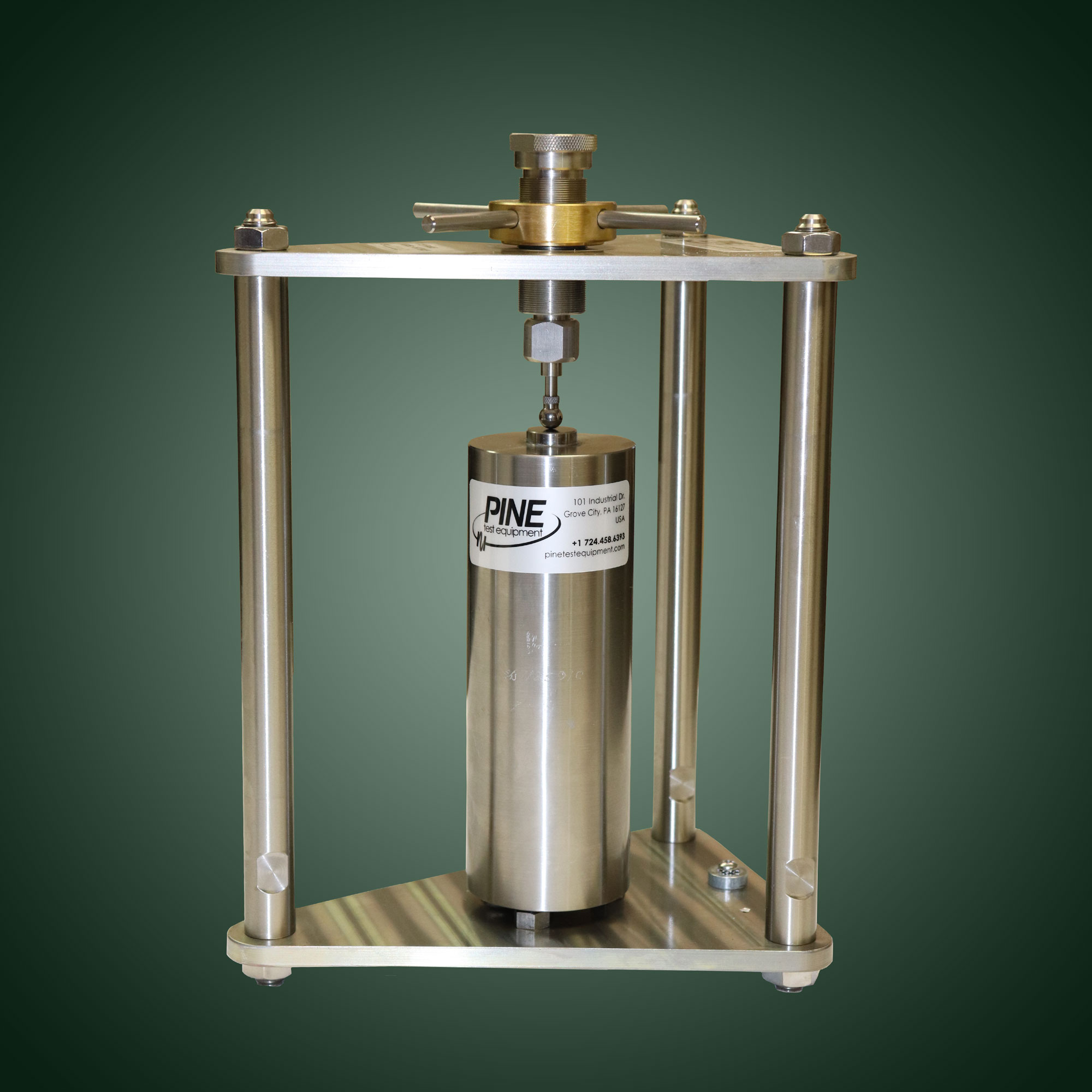
Specimen Fixture:
Corrosion resistant alloy with submersible LVDT
Verification Specimen:
304 Stainless Steel, 178.8 mm (7″) with ASTM E228 CTE
Calibration Specimen:
Titanium, 178.8 mm (7″) with ASTM E228 CTE
Input Parameters:
Specimen Length
Temperature Set Points
Equilibrium Requirement (i.e.: 0.00025mm/30 minutes)
Test Stop Criteria (i.e.: 0.3 micro-strain/°C)
Sample Identification
Data Acquisition:
Bath Temperature (4 channel)
Up to 3 Specimen Fixtures
Specimen Temperature (optional)
Minimum Computer Requirements:
1 GHz P4 or equivalent, 4 GB RAM, 10 MB Available HD Space
Microsoft® Windows® 11/10/8/7/XP SP3, 32-bit or 64-bit (English version required)
Microsoft® Excel® 2013 through 2021 ** Office 365 Excel is not supported at this time**
1024 x 768 minimum display resolution
Verification:
- Verification is used to maintain the traceability of a system and to determine when to recalibrate. If the machine response is in conformance, no correction is required and the system is considered calibrated.
- Verify the transducer displacement calibration every 3 months.
- Verify the Frame Correction Factor every 1 month.
- Verify the lengths of the calibration and verification specimens annually.
- Verify the system temperatures every month when the Frame Correction Factor is being verified.
Calibration:
Important Note: If a measurement system (force, angle, height) is shown to be correct when verified, it is considered fully calibrated. It is preferable to not update a stable system’s calibration data if it is correct so that system stability can be observed over time.
Traceability:
- The coefficient of thermal expansion of the titanium calibration specimen is traceable. It is used to calibrate the transducer displacement (stroke) and the Frame Correction Factor.
- The coefficient of thermal expansion of the 304 stainless steel verification specimen is traceable. It is used to verify the transducer displacement (stroke) and the Frame Correction Factor.
- The temperature of the system, in the water bath and at the circulator, is calibrated using a traceable thermometer.
Part Number
Part Description
RAHTDT
Digital Thermometer: -50º to 150º C, 0.001ºC resolution, ± 0.05ºC accuracy
Part Number
Part Description
ACCTE16
Water Bath Temperature Probe (S/N 111801 and up)
AFCTX01
Specimen Temperature Data Acquisition Module (includes one EXT44034 specimen probe with 90" leads)
EXT44034
Specimen Temperature Probe
RCWP3
Computer to operate the AFTC2. Computer specifications are as follows: Intel® Pentium® 4 Processor, Microsoft® Windows® 7, 19” Flat Panel Display, Keyboard, Mouse, Read/write CD, Ethernet network module, Microsoft® Office basic edition.
ACCTF27K
Replacement Anode Kit (3)
Cleaning:
- A clean machine is vital to getting accurate test results.
Maintenance:
The transducer:
- Clean the spring loaded shaft with isopropyl alcohol and a cotton swab on a weekly basis.
- Polish the shaft with a Scotch-Brite™ Ultra Fine Abrasive Pad to remove any scaling.
- Use a fine wire brush to ensure the vent hole on the transducer is clear.
- Work the probe on the transducer in and out to ensure smooth operation.
- Warning: Do not use WD-40™ or other penetrating solvents on the transducer shaft.
Specimen Contact Points:
- Polish the three specimen support buttons and the transducer ball tip with a Scotch-Brite™ Ultra Fine Abrasive Pad to remove any scaling.
Water Bath:
- Change the water every 2-3 weeks to minimize the buildup of scale deposits.
- Add Simple Green™ cleaner to the water bath on a yearly basis and circulate it to minimize calcium scaling in the circulator.
- Remove any obstructions caught on the circulator screen before each use.
Lubrication:
- Apply synthetic grease to the transducer’s shaft after it is cleaned each week.
What does one need to consider in choosing a location for this machine?
- Select a sturdy, level, preferably concrete and ground level floor.
- A nearby floor drain would be useful.
- Stay away from other test machines that apply cyclical or impact loading.
- Allow sufficient space around the machine to load and unload specimens from the water bath.
Does the length of the concrete specimen matter?
- The specification requires a specimen length of 175 mm to 180 mm.
- The frame correction factor should be recalculated using a calibration specimen of appropriate length if specimen length are outside this range.
The User Interface:
A user interfaces with the AFCT2 system on a Windows® based computer system.
Test Data Storage:
The AFCT2 system stores the technician’s identity, comments entered regarding a specific test, the serial number of each fixture being used in the test, the correction factor for each fixture being used, the frame calibration standard serial number used to calibrate each fixture, the frame calibration standard’s CTE, the frame calibration date, the frame verification date, the identification of each specimen being tested, the height (length) of each specimen being tested, the date of each measurement, the time of each measurement, the temperature set point for each measurement, the temperature, the LVDT displacement for each LVDT, on the Windows® system that runs it. These files can be moved to different computers by standard means of file sharing.
Test Data Viewing:
The AFCT2 provides for data to be viewed in the form of a CTE Report or as raw data in Microsoft® Excel®.
The CTE Report workbook also allows a user to determine and see the thermal expansion coefficient based on the temperature transition slope of the Texas DOT method TEX-428-A.
Test Data Printing:
Test data and reports can be printed through the normal print functions of the computer being used.
Multiple Test Specimens:
The Pine AFCT2 has the capacity to determine the coefficient of thermal expansion of three (3) concrete specimens at one time. The purchase of an AFCT2 unit includes the frame required to measure a single concrete specimen. Additional test frames may be purchased from Pine.
-
Specifications
Power:
AFCT2:
100-240 VAC, 1 Amp, 60 Hz, 1 ph
Circulator:
115 VAC (±10%), 16.4 Amps, 60 Hz, 1ph
230 VAC (±10%), 12.5 Amps, 50 Hz, 1phShipping Weight:
Approximately 136 kg (300 lbs)
Footprint:
Approximately 45″ D x 35″ W x 35.5″ H for the water-bath/circulator system
Allow additional space along the unit for an operator to load specimens.Data Output:
Formatted Excel® Spreadsheet
Time, Temperature, Change in Length, and CTE ValueWater Bath:
838 mm length x 406 mm width x 889 mm high (33” x 16” x 35”)
Capacity: 68 liters / 18 gallons (holds up to three fixtures)Circulator:
Temperature Range:
10° – 50°C (50°-122°F) with a resolution of ± 0.1°C
Performance:
Heating: 10° – 50° C ~3.5 hour
Cooling: 50° – 10° C ~2 hourSpecimen Size:
Diameter: 75 mm – 160 mm
Length: 177.8 mm (7.0”) ± 2.5 mm (± 0.1”) [175.3 mm – 180.3 mm] The system can handle 168 to 188-mm long specimens, but lengths outside of 175.3 to 180.3 mm require custom frame standards.Specimen Fixture:
Corrosion resistant alloy with submersible LVDT
Verification Specimen:
304 Stainless Steel, 178.8 mm (7″) with ASTM E228 CTE
Calibration Specimen:
Titanium, 178.8 mm (7″) with ASTM E228 CTE
Input Parameters:
Specimen Length
Temperature Set Points
Equilibrium Requirement (i.e.: 0.00025mm/30 minutes)
Test Stop Criteria (i.e.: 0.3 micro-strain/°C)
Sample IdentificationData Acquisition:
Bath Temperature (4 channel)
Up to 3 Specimen Fixtures
Specimen Temperature (optional)Minimum Computer Requirements:
1 GHz P4 or equivalent, 4 GB RAM, 10 MB Available HD Space
Microsoft® Windows® 11/10/8/7/XP SP3, 32-bit or 64-bit (English version required)
Microsoft® Excel® 2013 through 2021 ** Office 365 Excel is not supported at this time**
1024 x 768 minimum display resolution -
Features
The User Interface:
A user interfaces with the AFCT2 system on a Windows® based computer system.
Test Data Storage:
The AFCT2 system stores the technician’s identity, comments entered regarding a specific test, the serial number of each fixture being used in the test, the correction factor for each fixture being used, the frame calibration standard serial number used to calibrate each fixture, the frame calibration standard’s CTE, the frame calibration date, the frame verification date, the identification of each specimen being tested, the height (length) of each specimen being tested, the date of each measurement, the time of each measurement, the temperature set point for each measurement, the temperature, the LVDT displacement for each LVDT, on the Windows® system that runs it. These files can be moved to different computers by standard means of file sharing.
Test Data Viewing:
The AFCT2 provides for data to be viewed in the form of a CTE Report or as raw data in Microsoft® Excel®.
The CTE Report workbook also allows a user to determine and see the thermal expansion coefficient based on the temperature transition slope of the Texas DOT method TEX-428-A.
Test Data Printing:
Test data and reports can be printed through the normal print functions of the computer being used.
Multiple Test Specimens:
The Pine AFCT2 has the capacity to determine the coefficient of thermal expansion of three (3) concrete specimens at one time. The purchase of an AFCT2 unit includes the frame required to measure a single concrete specimen. Additional test frames may be purchased from Pine.
-
Accessories
Part Number
Part Description
ACCTE16
Water Bath Temperature Probe (S/N 111801 and up)
AFCTX01
Specimen Temperature Data Acquisition Module (includes one EXT44034 specimen probe with 90" leads)
EXT44034
Specimen Temperature Probe
RCWP3
Computer to operate the AFTC2. Computer specifications are as follows: Intel® Pentium® 4 Processor, Microsoft® Windows® 7, 19” Flat Panel Display, Keyboard, Mouse, Read/write CD, Ethernet network module, Microsoft® Office basic edition.
ACCTF27K
Replacement Anode Kit (3)
-
Verification/Calibration
Verification:
- Verification is used to maintain the traceability of a system and to determine when to recalibrate. If the machine response is in conformance, no correction is required and the system is considered calibrated.
- Verify the transducer displacement calibration every 3 months.
- Verify the Frame Correction Factor every 1 month.
- Verify the lengths of the calibration and verification specimens annually.
- Verify the system temperatures every month when the Frame Correction Factor is being verified.
Calibration:
Important Note: If a measurement system (force, angle, height) is shown to be correct when verified, it is considered fully calibrated. It is preferable to not update a stable system’s calibration data if it is correct so that system stability can be observed over time.
Traceability:
- The coefficient of thermal expansion of the titanium calibration specimen is traceable. It is used to calibrate the transducer displacement (stroke) and the Frame Correction Factor.
- The coefficient of thermal expansion of the 304 stainless steel verification specimen is traceable. It is used to verify the transducer displacement (stroke) and the Frame Correction Factor.
- The temperature of the system, in the water bath and at the circulator, is calibrated using a traceable thermometer.
Part Number
Part Description
RAHTDT
Digital Thermometer: -50º to 150º C, 0.001ºC resolution, ± 0.05ºC accuracy
-
Maintenance
Cleaning:
- A clean machine is vital to getting accurate test results.
*Maintenance:*
The transducer:
- Clean the spring loaded shaft with isopropyl alcohol and a cotton swab on a weekly basis.
- Polish the shaft with a Scotch-Brite™ Ultra Fine Abrasive Pad to remove any scaling.
- Use a fine wire brush to ensure the vent hole on the transducer is clear.
- Work the probe on the transducer in and out to ensure smooth operation.
- Warning: Do not use WD-40™ or other penetrating solvents on the transducer shaft.
Specimen Contact Points:
- Polish the three specimen support buttons and the transducer ball tip with a Scotch-Brite™ Ultra Fine Abrasive Pad to remove any scaling.
Water Bath:
- Change the water every 2-3 weeks to minimize the buildup of scale deposits.
- Add Simple Green™ cleaner to the water bath on a yearly basis and circulate it to minimize calcium scaling in the circulator.
- Remove any obstructions caught on the circulator screen before each use.
Lubrication:
- Apply synthetic grease to the transducer’s shaft after it is cleaned each week.
-
FAQs
What does one need to consider in choosing a location for this machine?
- Select a sturdy, level, preferably concrete and ground level floor.
- A nearby floor drain would be useful.
- Stay away from other test machines that apply cyclical or impact loading.
- Allow sufficient space around the machine to load and unload specimens from the water bath.
Does the length of the concrete specimen matter?
- The specification requires a specimen length of 175 mm to 180 mm.
- The frame correction factor should be recalculated using a calibration specimen of appropriate length if specimen length are outside this range.
-
Contact Us